Planning a new hillstreamtank

The forum for the very best information on loaches of all types. Come learn from our membership's vast experience!

Moderator: LoachForumModerators

User avatar
janma
Posts: 725
Joined: Mon Dec 11, 2006 9:34 am
Location: Vaasa, Finland
Contact:

Planning a new hillstreamtank

Post by janma » Mon May 07, 2007 9:52 am

I'm making some plans for a new tank for my hillstream's. Has anyone tried a similar setup? And could this work? Heres a sketch of the top view.

Image

So all the technique would be hidden behind a fake wall, would probably put a similar rock backround as I have in the old tank to the wall. The wall would be 3cm at outlet side and ~5 at the inlet from the back of the tank. There would be 3 X 800 L/h powerheads in different heights and an eheim outer filter to make some current, the powerhead would have sponges at the intakes. Dunno why I want the outlet side to be smaller but don't think there any harm with that, hopefully :roll:

-Janne

User avatar
Martin Thoene
Posts: 11186
Joined: Wed Dec 28, 2005 5:38 am
Location: Toronto.....Actually, I've been on LOL since September 1998

Post by Martin Thoene » Mon May 07, 2007 10:05 am

Your problem may come from the other plane. In other words if the tank is too tall your narrower outlet might cause water to back flow and kind of go around and around behind the wall, but in a vertical plane.

Many years ago I worked in a workshop with some crazy guys. For amusement during lunch times we built a compressed air powered system for flying aircraft around a pole.

I won't get into the technical side of it all, but the guy who originally did this used to have an outlet jet mounted on the outside of the fuselage of the model aircraft. We discovered that if you placed the outlet air jet inside the fuselage the high-pressure air blast confined in the larger tube would pull extra air in the front air intakes and substantially increase the max speed of the aircraft.

With modifications, we got planes up to over 70 mph around that pole :D

So theoretically, if you limited the water column height above the powerhead, it might increase the suck and more water might get ejected at the outlet end. Leave it full tank height and I don't think this will be particularly effective.

Martin.
Image Resistance is futile. You will be assimilated.

Image

User avatar
LES..
Posts: 296
Joined: Tue Jan 10, 2006 1:34 pm
Location: Surrey, UK
Contact:

Post by LES.. » Mon May 07, 2007 10:29 am

Good to see another addict!

Martin is spot on with the first problem, back flow behind the partition, you could solve this by routing the outflows from the pumps through a solid partition.

The second issue you will be fighting is the lack of a concentrated outflow, all the flow will be diffused across the whole of the tank. Your measurements put the tank at a very similar size to mine, with 2400 lph from the pumps you will get a turn over of 10.6 time the volume per hour, with the length of your tanks that translates to a linear speed of 0.0035 m/s. This is a long way off the grail of hillstream tanks meeting the 1m/s habitat these fish come from. I would be a little wary about the back pressure the pumps as they will pushing against the back glass of the tank, a baffle to guide the water round the corner would be advisable.

It is a workable design and if you go with some serious pumps (Tunze streams 6200) you might get close to the river effect :-)

User avatar
janma
Posts: 725
Joined: Mon Dec 11, 2006 9:34 am
Location: Vaasa, Finland
Contact:

Post by janma » Mon May 07, 2007 11:08 am

I'm alittle bit of an idiot so could you please draw a simple sketch of the correction of the backflow :oops: And got the idea of rounding the corner at a local forum too, with plexiglass.

The pumps need to be bigger, I agree. Thanks for the feedback.

-Janne

User avatar
Keith Wolcott
Posts: 720
Joined: Sun Mar 04, 2007 1:49 pm
Location: Charleston, Illinois USA

Post by Keith Wolcott » Mon May 07, 2007 11:21 am

Janne- I really like your idea. All hidden out of sight. Something to think about is the amount of flow. The concentrated jet streams of the powerheads will be behind the false wall so the flow that you get out front will be dispersed and spread out. Thus it will not seem to be nearly as much flow as is obtained from Martin's river manifold. On the other hand, your design allows for pumps that move a lot more water. Several Tunze pumps could really get the water moving.

To roughly calculate the speed of the water that will move across the front of the tank, you can do the following. Compute the area of the plane that the water travels through: depth times height which in your case is 40 cm by 55 cm, which is 2200 square cm. Take about half of that with the idea that roughly, the water is mostly moving across the front half of the tank. This gives 1100 square cm. Your 3 x 800 L/h powerheads pump 2.400 L/h. Multiplying by 1000 gives 2.400.000 cubic cm per hour. Divide this number by the 1100 that we got earlier to get about 2182 cm per hour moving across the front half of your tank. Divide by 60 to get about 36 cm per minute. Or .6 cm per second.

For comparison, one Tunze Turbelle Stream 6100 pump moves 12000 L/h which is 5 times the water that the 3 x 800 L/h pumps move, so the current speed would be 5 times as fast or about 181 cm per minute or 3 cm per second.

This is the difficulty that makes it hard to get real current in a tank. Real current, dispersed throughout the tank requires good sized pumps. These calculations also make it clear how good Martin's river manifold really is. I think in one of his articles he said that his goal was to have a system that is relatively inexpensive, uses readily obtainable parts, and gives a good current (not a quote, I'm paraphrasing from memory so I apologize to Martin if I don't have this quite correct). Martin succeeded wildly with his solution. The only disadvantage that I know of is that the current that the river manifold gives is not a evenly dispersed current (and if it was it would be too slow). This is actually a strength of his system because he effectively gets fast currents in parts of the tank.

To give some empirical data concerning the above calculations, my 75 gallon tank is close to the same size as your tank. I have two Tunze 6045 pumps which move 4500 L/h and two canister filters that move about 1500 L/h each. They are all set up to power the flow around a horizontal circle as in your planned setup (but with no false wall). That's a total of 12000 L/h so the current by the above calculations should be about 3 cm per second. When I time the movement of food particles across the front of the tank I get values between 4 and 9 cm per second. Why? The current is fastest along the outside of the tank and slowest in the center where it is virtually stopped. What we calculated above is average speed. Your setup should also get faster than the calculated average speed right at the front of the tank (and slower as you move back towards the false wall). I am pretty happy with the current in my tank. It is enough that it is obvious that it is moving along and the fish seem to like to play in the higher current areas (I only have giant danios, Serpae Tetras, and SAE's, but will add loaches in a couple of weeks).

To conclude, I think that you have a really good idea, but a potential problem is that once the current is dispersed and distributed somewhat evenly it will seem very slow indeed unless you put in some pumps that move a lot of water.

I hope that this is not too long and is maybe helpful.

User avatar
Keith Wolcott
Posts: 720
Joined: Sun Mar 04, 2007 1:49 pm
Location: Charleston, Illinois USA

Post by Keith Wolcott » Mon May 07, 2007 11:26 am

Yes, while I wrote my reply, Martin and LES already answered very wisely. I had not thought of the backflow problem either. The smaller you make the output space, the bigger the backflow problem is.

User avatar
Keith Wolcott
Posts: 720
Joined: Sun Mar 04, 2007 1:49 pm
Location: Charleston, Illinois USA

Post by Keith Wolcott » Mon May 07, 2007 11:33 am

Martin- Would the backflow problem also be solved (rather than limiting the water height) by having a stack of 3 or 4 pumps up the entire column of water height? And also have the output and input on each end of the false wall the same size.

User avatar
Martin Thoene
Posts: 11186
Joined: Wed Dec 28, 2005 5:38 am
Location: Toronto.....Actually, I've been on LOL since September 1998

Post by Martin Thoene » Mon May 07, 2007 1:12 pm

Possibly Keith, but my experience has been that the more pumps you put in the more heat you create so there's a detrimental pay-off which really comes home to roost in the Summer months.

With Janne's meshed off area one can use almost any pump because the high suction around the pump will not be near small fish. My experience with the Seio 1500 gph pump suggests to me that one of those or even better, a 2600 would be an option. No experience with the Tunze pumps.

The Seio outlet design distributes all its oomph over a wide area. The size of effective outlet on Janne's design spreads it even further so you need a huge amount of total water pumping to get a good current in the main tank.

If a Seio was used for instance it could be mounted to the bottom of the tank and a solid water deflector placed from its outlet angled up to near the water surface on the left end of the wall (as shown in Janne's drawing). That would need to fit the back of the wall and back of the tank fairly tightly for maximum effect.

Thanks for the comments on The R/T manifold. Its simplicity is one of its bonuses, but it's far from perfect. It just modifies the conventional use of conventional equipment. But it's also tweakable, modifiable and adaptable to whatever is available where you live. One of my concerns in the design was making it DIY repeatable.

Martin.
Image Resistance is futile. You will be assimilated.

Image

User avatar
LES..
Posts: 296
Joined: Tue Jan 10, 2006 1:34 pm
Location: Surrey, UK
Contact:

Post by LES.. » Mon May 07, 2007 1:44 pm

Hi Jannie,

See the little red line:
Image
This is supposed to represent a sheet of plastic or some other material that you can drill so that you can poke through outflow from the pump leaving the intake on the other side. Assuming you can seal this in so no water can come back past it you will eliminate any chance of back flow.

From having played with Tunze streams I believe that they will be well suited to being mounted like this.

Another option is to move the pumps to the other end of the wall:
Image
but all this does is recreate Martin's manifold design but using a sectioned off part of the tank in place of the pipework.

User avatar
janma
Posts: 725
Joined: Mon Dec 11, 2006 9:34 am
Location: Vaasa, Finland
Contact:

Post by janma » Mon May 07, 2007 2:16 pm

Ok, now we're getting somewhere :) Thanks!
This is supposed to represent a sheet of plastic or some other material that you can drill so that you can poke through outflow from the pump leaving the intake on the other side.
This is possible, I already have an idea what to use. I think I'll make the inlet and outlet holes the same size, smells like trouble with different sizes. Or how about turning it around, outlet bigger?!? Feel like a nutty proffesor. Would be so cool to have some computer program that could simulate all this without needing to buld something that might flopp.

-Janne

User avatar
Keith Wolcott
Posts: 720
Joined: Sun Mar 04, 2007 1:49 pm
Location: Charleston, Illinois USA

Post by Keith Wolcott » Mon May 07, 2007 3:05 pm

Good point about the heat Martin.

User avatar
janma
Posts: 725
Joined: Mon Dec 11, 2006 9:34 am
Location: Vaasa, Finland
Contact:

Post by janma » Tue May 08, 2007 8:24 am

Small modifications done. Ive been looking into some pumps too, found some good possibilites. And while surfing the web I found this http://www.geocities.com/river_tank/ I started juggling with the thought of the idea of small waterfalls, similar to the ones in the url and it would raise the oxygen level in the tank too. I'll have to make some good drawings with different options.

Image

-Janne

User avatar
janma
Posts: 725
Joined: Mon Dec 11, 2006 9:34 am
Location: Vaasa, Finland
Contact:

Post by janma » Tue Jul 03, 2007 2:05 pm

Ok, back to planning again. This time it will be done, we're moving so time for some plumbing. Came to the conclusion that I'll stick with the old tank. Got me a second Hydor Seltz L45II pump (
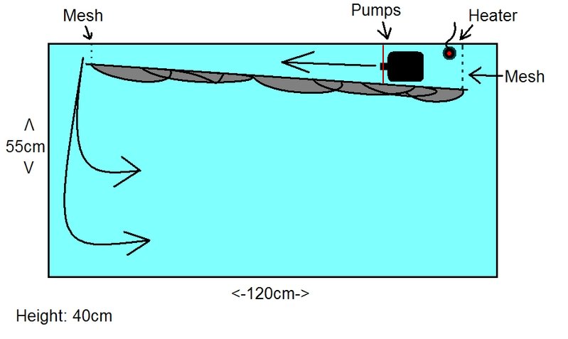
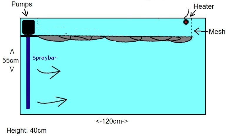
http://www.marinedepot.com/md_viewItem. ... ct=HD10202), because I have the PVC pipes that fit to it. Made a really bad picture of the plan, hope you get some idea of where I'm going with it. There's no real scale to the picture, paintbrush isn't really the best program for blueprints :P

UP and SIDE-views
Image

As drawn in the picture the outlet is not holes but horizontal cuts, made some experimenting with different types of outlet holes and liked this option the best. Also placing the pump and sponges at one end and only pipes sticking out in the other end, which can be easily camouflaged. At the same side as the pump there will be a embankment where Pogostemon helferi will be planted. As you can guess the empty gap between the outlet and embankment will be filled with rocks, LOTS of rocks. Other technique will be an air pump and the EHEIM outer filter, no heater. The only problem now is the embankment, how would be the best way to build it so the sand wont flow out. Considering rocks and stockings filled with sand. Have 4 weeks to figure things out.
-Janne

User avatar
janma
Posts: 725
Joined: Mon Dec 11, 2006 9:34 am
Location: Vaasa, Finland
Contact:

Post by janma » Mon Oct 29, 2007 2:58 pm

Time for some planning again. :roll:

I've had the tank running with the system I've drawn above now for over 2 months. Worked just fine, but one of the pumps has started make some annoying noise and is resonating some how. So I've decided to take up the challenge again to build this.

Image

The place for pumps and other equipment is divided to two spaces. I will use the same pumps as before and no heater, temp is about 24celsius without it. The tank will be only 30cm high. The suction end will either have some mesh or foam. A part of the outlet end will be covered on top, so there is only one way for the water to go. Also considering putting one of the pumps on a timer so the flow rate won't always be the same.

Keith W, could you use some of mathematical skills here again. The two pumps outputs are 3500l/h each and the external filter ~600l/h. The tank is much lower (maybe 25cm with substrate or less) and the depth will be about 40cm, in my non-mathematical way of thinking: there should be some current. But will there actually be some current or should I get bigger pumps?
-Janne

User avatar
Keith Wolcott
Posts: 720
Joined: Sun Mar 04, 2007 1:49 pm
Location: Charleston, Illinois USA

Post by Keith Wolcott » Tue Oct 30, 2007 5:23 am

Janma- If I understand correctly you are talking about a flow across a cross-section of water (say from right to left) that is 25 cm tall and 40 cm deep (front to the false wall on the back on the tank). That is 25x40 = 1000 cm^2. Your pumps are moving 3500 + 3500 + 600 = 7600 l/hr (is it really that much?). This is 7600000 cm^3 per hr. Dispersed over the 1000 cm^2 cross-section, this is a flow of 7600 cm/hr or about 2.1 cm per second. Picture a particle of fish food moving across the front of the tank at 2.1 cm per second. That is really slow.

The above assumes that there is no back flow problem as Martin has pointed out earlier. It also assumes that the flow is completely spread evenly which is not really true. You will have a stronger flow where it comes out from the back around the corner and probably stronger right at the front glass , but weaker right in front of the false wall.

I am not trying to discourage you with your very nice idea of hiding the pumps, but it is the case that getting a fast dispersed flow across the front requires very large pumps. Even if you quadrupled your pump power it would still be only 8.4 cm per second which is still quite slow. Ten times the pumping power gets you to 21 cm per second which is starting to sound like something, but your loaches would still hardly notice it. Martin's manifold has both strong concentrated flow and dispersed flow which is what makes it so effective. The same is true for the circular flows that others have used. Maybe your system, plus a river manifold, or your system plus an extra pump shooting a concentrated flow across the front of the tank would be good. That way some of your pumps are hidden, but you still get both concentrated and dispersed flow.

Good luck!

Post Reply

Who is online

Users browsing this forum: No registered users and 361 guests